This section provides a comprehensive guide to understanding and working with 3-way dimmer switch wiring diagrams․ It covers the basics, installation, and functionality, ensuring safe and efficient setups for your lighting needs․
1․1 What is a 3-Way Dimmer Switch?
A 3-way dimmer switch is an electrical device designed to control lighting from two different locations․ Unlike a standard dimmer, which only has two terminals (input and output), a 3-way dimmer has three terminals, enabling it to connect with a second switch․ This setup allows for precise control over light intensity and on/off functionality from multiple points․ The switch operates using a traveler wire system, which connects the two switches and facilitates communication between them․ It is commonly used in hallways, staircases, or large rooms where dual control is beneficial․ The dimmer function adds the advantage of adjustable brightness, enhancing energy efficiency and ambiance․ Understanding its functionality is crucial for proper installation and use․
1․2 Importance of Wiring Diagrams for 3-Way Dimmer Switches
Wiring diagrams are essential for the safe and correct installation of a 3-way dimmer switch․ They provide a visual representation of the electrical connections, ensuring that each wire is correctly identified and connected․ Without a diagram, the complex setup of the traveler wire system, neutral, load, and ground wires can become confusing, leading to potential safety hazards or system malfunctions․ Diagrams also help in troubleshooting common issues, such as flickering lights or non-responsive dimmers․ By following a wiring diagram, homeowners and electricians can avoid errors, save time, and ensure that the dimmer switch operates efficiently․ These guides are particularly useful for DIY enthusiasts, offering clarity and confidence during the installation process․ They are indispensable tools for achieving a successful and professional-grade setup․
1․3 Benefits of Using a Dimmer Switch
A dimmer switch offers numerous benefits, enhancing both functionality and energy efficiency․ It allows for precise control over light levels, creating customizable ambiance for various settings․ By adjusting brightness, dimmers reduce energy consumption, lowering utility bills and extending bulb life․ They also add a modern aesthetic to interiors, boosting home value․ With smooth transitions between light levels, dimmers minimize flickering and provide a more comfortable environment․ Additionally, they are versatile, supporting multiple lighting fixtures and configurations․ These advantages make dimmer switches a practical and stylish upgrade for any space, offering convenience, efficiency, and enhanced user experience․ Their installation, guided by wiring diagrams, ensures optimal performance and safety, making them a worthwhile investment for homeowners and businesses alike․

Understanding 3-Way Switches
3-way switches are essential for controlling lights from multiple locations․ They use three terminals and traveler wires to connect two switches, enabling seamless light operation from different points․ This setup is common in hallways and staircases, offering convenience and flexibility․ Proper wiring is crucial for their functionality, ensuring reliable and safe performance․ Understanding their mechanics is key to successful installation and troubleshooting, making them a fundamental component in modern electrical systems․ This section delves into their structure and operation, providing a solid foundation for working with these switches effectively․ Their role in dimmer configurations further enhances their utility, catering to various lighting needs․
2․1 Definition and Functionality
A 3-way dimmer switch is a component designed to control lighting from multiple locations․ Unlike a standard single-pole switch, it uses three terminals and traveler wires to connect two switches, enabling seamless light operation from different points․ This setup is ideal for hallways, staircases, and large rooms where dual control is beneficial․ The switch routes power through the traveler wires, allowing the light fixture to be turned on or off from either location․ The dimmer functionality adds the ability to adjust brightness, enhancing ambiance and energy efficiency․ Proper wiring is essential for safe and reliable operation․ Understanding the definition and functionality of a 3-way dimmer switch is crucial for successful installation and troubleshooting, ensuring it meets your lighting needs effectively․ This section provides a clear overview of its inner workings and practical applications․
2․2 Components of a 3-Way Dimmer Switch
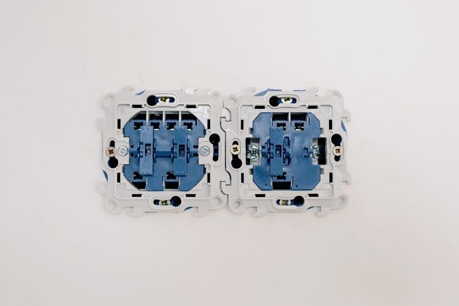
A 3-way dimmer switch consists of several key components essential for its functionality․ The switch features three terminals: two for the traveler wires and one for the common wire․ These terminals allow the switch to connect with another 3-way switch, enabling control from multiple locations․ The dimmer mechanism includes a variable resistor or electronic components to adjust brightness․ The switch also includes a ground terminal for safety and a neutral wire connection to complete the circuit․ The traveler wires are typically colored black or red, while the common wire is often brass or copper․ The dimmer’s internal components work together to regulate power to the light fixture, providing smooth dimming control․ Understanding these parts is crucial for proper installation and troubleshooting․ This section details each component’s role in the overall operation of the switch․
2․3 The Traveler Wire System
The traveler wire system is a critical component in 3-way dimmer switch wiring, enabling control of a light fixture from two locations․ This system uses three wires: two traveler wires (typically red and black) and a common wire (usually brass or copper)․ The traveler wires connect the two 3-way switches, allowing them to communicate and control the light․ The common wire is connected to the light fixture, completing the circuit․ Proper identification and connection of these wires are essential for the system to function correctly․ Miswiring can lead to malfunction or safety hazards․ This section explains how the traveler wire system operates and its role in enabling multi-location control for lighting fixtures․ Understanding this system is vital for successful installation and troubleshooting of 3-way dimmer switches․ Always refer to a wiring diagram for specific connections․

Safety Precautions and Tools Needed
Safety precautions involve turning off the power supply and testing for voltage․ Essential tools include wire strippers, needle-nose pliers, and a voltage tester․ Always follow safety guidelines to avoid electrical hazards․
3․1 Turning Off the Power Supply
Turning off the power supply is the first and most crucial step in any electrical installation․ Locate the circuit breaker or fuse box that controls the lighting circuit you’re working on․ Switch off the breaker or remove the appropriate fuse to ensure no electricity flows to the wires․ Verify the power is off using a voltage tester on all wires connected to the switches․ This step prevents electric shocks, injuries, or fatalities․ Never rely on the light being off as confirmation; always test with a voltage tester․ Keep the breaker off until you’ve completed the installation and are ready to test the system․ Safety should always be your top priority when handling electrical systems․
3․2 Testing for Voltage
Testing for voltage is a critical safety step before starting any electrical work․ Use a voltage tester to ensure no power is present at the switch or wires․ Turn off the circuit breaker and verify the power is off using the tester on all wires․ This prevents accidental shocks or injuries․ A non-contact voltage tester is ideal for this task, as it detects electricity without touching wires․ Always test both the live and neutral wires to confirm they are de-energized․ If the tester lights up or beeps, it indicates the presence of voltage, and you must wait until it is safe to proceed․ Never assume the power is off without testing, as this can lead to dangerous situations․ Proper voltage testing ensures a safe working environment for your dimmer switch installation․
3․3 Essential Tools for Installation
Installing a 3-way dimmer switch requires specific tools to ensure safety and efficiency․ A voltage tester is essential to confirm power is off before starting work․ Needle-nose pliers and screwdrivers (both flathead and Phillips) are necessary for wire connections and switch removal․ Wire strippers may be needed if exposing new wire ends․ A ladder or step stool is useful for accessing high switches․ Always use a non-contact voltage tester to verify no electricity is present; Keep a circuit breaker or fuse box tool handy to safely turn off power․ Proper tools ensure a secure and professional installation, reducing risks of electrical hazards․ Gather all tools beforehand to streamline the process and avoid delays during wiring․
Reading and Interpreting Wiring Diagrams
Understanding wiring diagrams is crucial for safe and accurate installation․ These diagrams use standardized symbols to represent components like switches, lights, and wires․ Hot wires are typically black or red, while neutral wires are white, and ground wires are bare or green․ Traveler wires are key in 3-way systems, connecting switches to control lighting from multiple locations․ Familiarizing yourself with these elements ensures proper connections and avoids electrical hazards․ Always cross-reference diagrams with your specific setup to confirm wire roles and configurations․
4․1 Understanding Symbols and Colors
In 3-way dimmer switch wiring diagrams, symbols and colors play a vital role in identifying components and their functions; A circle often represents a light fixture, while a rectangle may denote a switch․ Lines symbolize wires, and their colors indicate their purpose: black or red for “hot” wires, white for neutral, and green or bare copper for ground․ Traveler wires, essential in 3-way systems, are typically marked with distinct colors to differentiate them․ These visual representations simplify the complexity of wiring, ensuring accurate connections․ By deciphering these symbols and colors, you can navigate the diagram confidently, understanding how power flows through the circuit and how components interact․ This foundational knowledge is key to successful installation and troubleshooting․
4․2 Identifying Line, Load, Neutral, and Ground Wires
In a 3-way dimmer switch wiring diagram, correctly identifying wires is crucial․ The line wire (typically black or red) carries power from the electrical source․ The load wire connects to the light fixture, distributing power․ The neutral wire (usually white) completes the circuit, while the ground wire (green or bare copper) ensures safety by grounding the system․ Traveler wires, often red or black, facilitate communication between switches․ Properly distinguishing these wires ensures safe and functional connections․ Misidentification can lead to circuit malfunctions or hazards․ Always refer to the diagram and test wires with a voltage tester to confirm their roles before proceeding with installation․ This step is critical for ensuring the dimmer switch operates correctly and safely in a 3-way configuration․
4․3 Common Configurations in 3-Way Wiring
In 3-way wiring, common configurations involve the use of traveler wires to connect switches․ The line wire (hot) from the power source connects to one switch, while the load wire goes to the light fixture․ The traveler wires (red and black) link the switches, enabling control from multiple locations․ Neutral and ground wires are also essential for completing the circuit and ensuring safety․ Configurations vary based on the power source location—either at the first switch or the light fixture․ Properly connecting these wires ensures smooth operation of the dimmer switch․ Understanding these setups is key for successful installation and troubleshooting․ Always refer to the wiring diagram to confirm the correct connections for your specific setup, ensuring functionality and safety in your lighting system․

Step-by-Step Wiring Process
Start by turning off the power and testing for voltage․ Connect the line wire to the dimmer, link the traveler wires between switches, and secure neutral and ground connections․ Ensure all wires are properly fastened to the correct terminals for safe and efficient operation․
5․1 Preparing the Dimmer Switch
Before installation, ensure the dimmer switch is compatible with your lighting setup․ Refer to the manufacturer’s wiring diagram to identify terminals․ Remove any packaging and pre-install brackets if necessary․ Verify the switch’s maximum wattage rating matches your light fixtures․ Gently pull out the switch from its casing to access the terminal screws․ Label the wires according to the diagram to prevent confusion․ Ensure all wires are stripped of insulation at the ends․ Finally, double-check the switch’s orientation to align with your wiring configuration․ Proper preparation ensures a smooth and error-free installation process․
5․2 Connecting the Traveler Wires
To connect the traveler wires, identify the two wires linking the dimmer switches, typically red and black․ Attach one traveler to each brass terminal on the dimmer․ Ensure the common wire, usually black, connects to the darker terminal․ Verify connections match the wiring diagram․ Tighten all terminals securely․ Use a voltage tester to confirm no power is present․ Label wires if needed for clarity․ Double-check connections before proceeding to neutral and ground wires․ This step is crucial for proper communication between switches, allowing them to control the light fixture effectively․ Ensure accuracy to avoid malfunctions and maintain safety throughout the installation process․
5․3 Neutral and Ground Wire Connections
Connect the neutral wire (usually white) to the neutral terminal on the dimmer switch․ Ensure it is securely fastened to prevent loose connections․ Next, attach the ground wire (bare copper) to the grounding terminal, typically located on the back or bottom of the dimmer․ This step is critical for safety, as it provides a path to ground for fault currents․ Tighten all terminals firmly to avoid any electrical issues․ Double-check the wiring diagram to confirm the correct placement of these wires․ After completing these connections, use a voltage tester to verify the circuit is safe and functioning properly․ Proper neutral and ground connections are essential for the dimmer switch to operate correctly and safely․
5․4 Finalizing the Dimmer Switch Installation
Once all connections are made, carefully tuck the wires back into the wall box and secure the dimmer switch with the provided mounting screws․ Tighten the terminals firmly to ensure reliable connections․ Replace the wall plate and turn the power back on at the circuit breaker․ Test the dimmer switch to ensure it operates smoothly, adjusting brightness levels and verifying proper function․ Double-check the wiring against the diagram to confirm accuracy․ If any issues arise, such as flickering lights, revisit the connections to ensure they are secure and correctly configured․ Proper installation ensures safe and efficient operation of your 3-way dimmer switch, providing reliable lighting control for years to come․

Troubleshooting Common Issues
Identify issues like flickering lights or non-responsive dimmers by checking connections and ensuring wiring matches the diagram․ Correcting loose wires or misconfigured setups typically resolves problems efficiently․
6․1 Flickering Lights
Flickering lights are a common issue in 3-way dimmer setups, often caused by loose wire connections or improper installation․ Check terminals for tightness and ensure wires are securely fastened․ Incorrect wiring, such as misconnected traveler wires, can also cause flickering․ Verify connections against the wiring diagram to ensure accuracy․ Additionally, compatibility issues with bulb types or dimmer capacity may contribute to flickering․ Test with different bulbs or consult the manufacturer’s guidelines for compatibility․ If flickering persists, inspect the dimmer switch for damage or wear․ Addressing these issues promptly ensures reliable performance and safety in your lighting system․
6․2 Dimmer Not Responding
If the dimmer fails to respond, ensure the power supply is turned off at the circuit breaker; Verify that the dimmer switch is properly connected to the correct wires, as shown in the wiring diagram․ Use a voltage tester to confirm there is no power present before handling wires․ Check for loose connections or incorrect wiring, particularly with traveler wires․ Ensure the dimmer is compatible with the bulb type and wattage; If issues persist, consult the manufacturer’s guidelines or seek assistance from a licensed electrician to resolve the problem effectively․
6․3 Incorrect Wiring Connections
Incorrect wiring connections are a common issue when installing a 3-way dimmer switch․ Ensure the line, load, neutral, and ground wires are properly identified and connected as per the wiring diagram․ Misconnecting the traveler wires can lead to malfunctioning dimmers or lights․ Always refer to the wiring diagram to confirm the correct terminals for each wire․ If the dimmer does not function correctly, check for reversed connections or loose wires․ Turn off the power supply before inspecting or adjusting any connections․ Use a voltage tester to ensure no power is present․ Correcting wiring errors requires careful attention to detail and adherence to the provided wiring diagram to ensure proper operation of the dimmer switch and safety․

Advanced Configurations
Explore advanced setups like 4-way dimmer switch wiring and controlling multiple light fixtures․ These configurations offer enhanced flexibility and customization for complex lighting systems, ensuring precise control and energy efficiency․
7․1 4-Way Dimmer Switch Wiring
A 4-way dimmer switch wiring configuration involves an additional control point compared to a 3-way setup․ This advanced method is ideal for larger spaces or complex lighting systems, allowing control from three or more locations․ The wiring requires a four-wire cable (including ground) to connect the switches, ensuring smooth communication between all dimmers․ The process builds on the 3-way traveler wire system but introduces an extra switch, enabling more flexibility․ Proper wiring is crucial to avoid flickering or malfunctioning lights․ Always refer to a wiring diagram for precise connections, and ensure all wires are correctly labeled and matched to their respective terminals․ This setup offers enhanced control and energy efficiency for modern lighting needs․
7․2 Dimmer Switches for Multiple Light Fixtures
Dimmer switches can efficiently control multiple light fixtures, offering enhanced flexibility and energy savings․ This setup is ideal for rooms with several lamps or lighting zones․ By connecting multiple fixtures to a single dimmer, you can adjust brightness uniformly across all lights․ The wiring process involves linking the fixtures in parallel, ensuring each receives the same voltage․ The dimmer switch acts as the central control point, regulating power distribution․ Proper wiring diagrams are essential to ensure safe and correct connections․ When installing, always turn off the power supply and use a voltage tester․ This configuration is perfect for modern homes seeking advanced lighting solutions․ It allows for seamless control and customization of lighting levels, enhancing both ambiance and functionality․
8․1 Summary of Key Points
Understanding the wiring process for a 3-way dimmer switch is essential for achieving proper lighting control․ Key steps include planning the circuit, ensuring safety by turning off power, and correctly identifying wires․ The traveler wire system is crucial for enabling communication between switches․ Always refer to a wiring diagram to avoid errors․ Benefits of a dimmer switch include energy efficiency, extended bulb life, and customizable lighting levels․ Proper installation ensures reliability and safety, while incorrect wiring can lead to malfunctions․ By following guidelines and using the right tools, you can successfully install a 3-way dimmer switch and enjoy enhanced lighting control in your home or workspace․ This summary highlights the core aspects of the process for a smooth experience․
8․2 Final Thoughts on 3-Way Dimmer Switch Wiring
Installing a 3-way dimmer switch is a rewarding DIY project that enhances lighting control and energy efficiency․ Proper planning and adherence to wiring diagrams are vital to avoid complications․ Always prioritize safety by turning off power and testing wires․ The traveler wire system is key to enabling smooth communication between switches․ Dimmer switches not only save energy but also extend bulb life and provide customizable lighting․ Troubleshooting common issues like flickering or unresponsive dimmers can often be resolved by checking connections․ With patience and attention to detail, you can successfully install a 3-way dimmer switch and enjoy the benefits of advanced lighting control․ Consider exploring advanced configurations for multiple fixtures or 4-way setups to further enhance your lighting system․
Additional Resources
Refer to the 3-way dimmer switch wiring diagram PDF for detailed instructions․ Additional guides and videos are available online for advanced configurations and troubleshooting․
- 3-Way Wiring Diagram PDF
- Mechanical Switch Wiring Guide
- Accessory Switch Tutorial
- Lutron Dimmer Installation Video
9․1 Recommended PDF Guides
For detailed instructions, download the 3-way dimmer switch wiring diagram PDF, which includes step-by-step guides and diagrams․ Additional resources like the 3-Way Wiring with a Mechanical Switch PDF and 3-Way Wiring with an Accessory Switch PDF provide comprehensive insights․ These guides cover various configurations, such as 4-way wiring and multiple light fixtures․ They also include troubleshooting tips and safety precautions․ The Lutron 3-Way Dimmer Installation Diagram is another excellent resource, offering clear visuals and instructions․ Ensure to refer to these PDFs for a smooth and safe installation process․ They are available online and cater to both DIY enthusiasts and professionals․
- 3-Way Dimmer Switch Wiring Diagram PDF
- Mechanical Switch Wiring Guide
- Accessory Switch Tutorial
9․2 Online Tutorials and Videos
Enhance your understanding with online tutorials and videos that demonstrate 3-way dimmer switch wiring․ Websites like YouTube offer step-by-step guides, while platforms like Vimeo provide detailed walkthroughs․ Many manufacturers, such as Lutron, offer video tutorials specifically for their dimmer switches․ These resources often include real-time demonstrations, making complex wiring tasks easier to grasp․ Additionally, forums like Reddit and specialized electrical websites share user experiences and tips for troubleshooting common issues․ Online tutorials are particularly useful for visual learners, as they provide a hands-on approach to understanding the wiring process․ They also cover advanced configurations, such as 4-way dimmer setups and multi-light fixture controls․
- Lutron 3-Way Dimmer Tutorial
- YouTube Wiring Guide
- Advanced Dimmer Configurations

